


Dongguan Phynam Comtech Co.,Limited
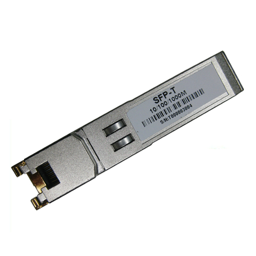
SFP-T 1000BASE-T and 10/100/1000BASE-T Copper SFP Transceiver PH-GLC-T
Features
0°C to +70°C (Commercial) or -20°C to +85°C (Extend)
Applications
Description
SFP-T 1000BASE-T and 10/100/1000BASE-T Copper Small Form Pluggable (SFP)transceivers is high performance, cost effective module compliant with the Gigabit Ethernet and 1000BASE-T standards as specified in IEEE 802. 3-2002 and IEEE 802.3ab, which supp- orting 1000Mbps data- rate up to 100 meters reach over unshielded twisted-pair category 5 cable. The module supports1000 Mbps full duplex data-links with 5-level Pulse Amplitude Modulation (PAM) signals. All four pairs in the cable are used with symbol rate at 250Mbps on each pair. The module provides standard serial ID information compliant with SFP MSA, which can be accessed with address of A0h via the 2wire serial CMOS EEPROM protocol. The physical IC can also be accessed via 2wire serial bus at address ACh.
Pin Definitions
Pin Diagram
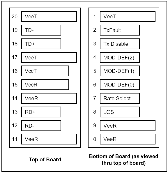
Figure 1. Pin Definitions
Pin Descriptions
|
Pin |
Signal Name |
Description |
Plug Seq. |
Notes |
|
1 |
VEET |
Transmitter Ground |
1 |
|
|
2 |
TX FAULT |
Transmitter Fault Indication |
3 |
Note1 |
|
3 |
TX DISABLE |
Transmitter Disable |
3 |
Note2 |
|
4 |
MOD_DEF(2) |
SDA Serial Data Signal |
3 |
Note3 |
|
5 |
MOD_DEF(1) |
SCL Serial Clock Signal |
3 |
Note3 |
|
6 |
MOD_DEF(0) |
TTL Low |
3 |
Note3 |
|
7 |
Rate Select |
Not Connected |
3 |
|
|
8 |
LOS |
Loss of Signal |
3 |
Note4 |
|
9 |
VEER |
Receiver ground |
1 |
|
|
10 |
VEER |
Receiver ground |
1 |
|
|
11 |
VEER |
Receiver ground |
1 |
|
|
12 |
RX- |
Inv. Received Data Out |
3 |
Note 5 |
|
13 |
RX+ |
Received Data Out |
3 |
Note 5 |
|
14 |
VEER |
Receiver ground |
1 |
|
|
15 |
VCCR |
Receiver Power Supply |
2 |
|
|
16 |
VCCT |
Transmitter Power Supply |
2 |
|
|
17 |
VEET |
Transmitter Ground |
1 |
|
|
18 |
TX+ |
Transmit Data In |
3 |
Note 6 |
|
19 |
TX- |
Inv. Transmit Data In |
3 |
Note 6 |
|
20 |
VEET |
Transmitter Ground |
1 |
Notes:
Plug Seq.: Pin engagement sequence during hot plugging.
1) TX Fault is not supported and is always connected to ground.
2) TX disable, an input used to reset the transceiver module, This pin is pulled up within the module with a 4.7 KΩ resistor.
Low (0 – 0.8 V): Transceiver on
Between (0.8 V and 2.0 V): Undefined
High (2.0 – 3.465 V): Transceiver in reset state
Open: Transceiver in reset state
3) Mod-Def 0,1,2. These are the module definition pins. They should be pulled up with a 4.7K~10K resistor on the host board. The pull-up voltage shall be VccT or VccR
Mod-Def 0 is grounded by the module to indicate that the module is present
Mod-Def 1 is the clock line of two wire serial interface for serial ID
Mod-Def 2 is the data line of two wire serial interface for serial ID
4) RX_LOS (Loss of Signal): LVTTL compatible with a maximum voltage of Host_Vcc. RX_LOS can enabled or disabled (Refer to Ordering information),RX_LOS is not used and is always tied to ground via 100-ohm resistor.
5) RD-/+: These are the differential receiver outputs. They are AC coupled 100 differential lines which should be terminated with 100 (differential) at the user SERDES.
6) TD-/+: These are the differential transmitter inputs. They are AC-coupled, differential lines with 100 differential termination inside the module.
+3.3V Volt Electrical Power Interface
|
+3.3V volt Electrical Power Interface |
||||||
|
Parameter |
Symbol |
Min |
Typ |
Max |
Units |
Notes/Conditions |
|
Supply Current |
Is |
320 |
375 |
mA |
1.2W max power over full range of voltage and temperature. See caution note below |
|
|
Input Voltage |
Vcc |
3.13 |
3.3 |
3.47 |
V |
Referenced to GND |
|
Maximum Voltage |
Vmax |
4 |
V |
|||
Low-speed signals, electronic characteristics
|
Low-Speed Signals, Electronic Characteristics |
|||||
|
Parameter |
Symbol |
Min |
Max |
Units |
Notes/Conditions |
|
SFP Output LOW |
VOL |
0 |
0.5 |
V |
4.7k to 10k pull-up to host_Vcc, measured at host side of connector |
|
SFP Output HIGH |
VOH |
host_Vcc - 0.5 |
host_Vcc + 0.3 |
V |
4.7k to 10k pull-up to host_Vcc, measured at host side of connector |
|
SFP Input LOW |
VIL |
0 |
0.8 |
V |
4.7k to 10k pull-up to Vcc, measured at SFP side of connector |
|
SFP Input HIGH |
VIH |
2 |
Vcc + 0.3 |
V |
4.7k to 10k pull-up to Vcc, measured at SFP side of connector |
High-speed electrical interface, transmission line-SFP
|
High-Speed Electrical Interface Transmission Line-SFP |
||||||
|
Parameter |
Symbol |
Min |
Typ |
Max |
Units |
Notes/Conditions |
|
Line Frequency |
fL |
125 |
MHz |
5-level encoding, per IEEE 802.3 |
||
|
Tx Output Impedance |
Zout,TX |
100 |
Ohm |
Differential, for all Frequencies between 1MHz and 125MHz |
||
|
Rx Input Impedance |
Zin,RX |
100 |
Ohm |
Differential, for all Frequencies between 1MHz and 125MHz |
||
High-speed electrical interface, host-SFP
|
High-Speed Electrical Interface, Host-SFP |
||||||
|
Parameter |
Symbol |
Min |
Typ |
Max |
Units |
Notes/Conditions |
|
Single ended data input swing |
Vinsing |
250 |
1200 |
mV |
Single ended |
|
|
Single ended data output swing |
Voutsing |
350 |
800 |
mV |
Single ended |
|
|
Rise/Fall Time |
Tr,Tf |
175 |
psec |
20%-80% |
||
|
Tx Input Impedance |
Zin |
50 |
Ohm |
Single ended |
||
|
Rx Output Impedance |
Zout |
50 |
Ohm |
Single ended |
||
General specifications
|
General |
||||||
|
Parameter |
Symbol |
Min |
Typ |
Max |
Units |
Notes/Conditions |
|
Data Rate |
BR |
10 |
1000 |
Mb/sec |
IEEE 802.3 compatible. See Notes 2 through 4 below |
|
|
Cable Length |
L |
100 |
m |
Category 5 UTP. BER <10-12 |
||
Notes:
1. Clock tolerance is +/- 50 ppm
2. By default, the SFP-T 1000BASE-T and 10/100/1000BASE-T is a full duplex device in preferred master mode
3. Automatic crossover detection is enabled. External crossover cable is not required
Environmental specifications
|
Parameter |
Symbol |
Min |
Typical |
Max |
Unit |
|
|
Operating Case Temperature |
Commercial |
Tc |
0 |
+70 |
°C |
|
|
Extend |
-20 |
+85 |
°C |
|||
|
Storage Temperature |
-40 |
+85 |
°C |
|||
Mechanical Specifications
The host-side of the SFP-T 1000BASE-T and 10/100/1000BASE-T conforms to the mechanical specifications outlined in the SFP MSA1. The front portion of the SFP (part extending beyond the face plate of the host) is larger to accommodate the RJ-45 connector.
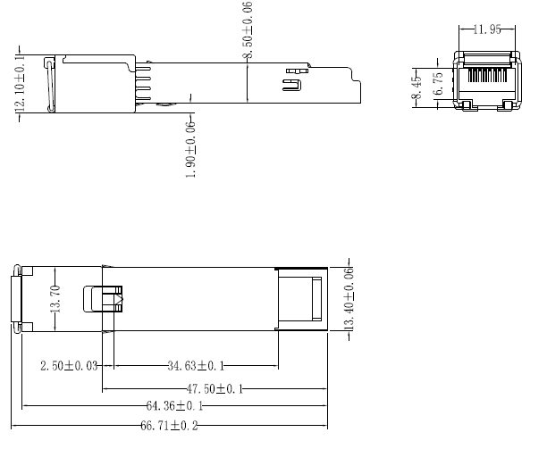
Figure 2. Mechanical dimensions
SFP-Coper transceiver is designed to be Class I Laser safety compliant and is certified per the following standards:
|
Feature |
Agency |
Standard |
Certificate / Comments |
|
Environmental protection |
SGS |
RoHS Directive 2002/95/EC |
GZ090319751A/CHEM |
