


Dongguan Phynam Comtech Co.,Limited
1.25Gbps SFP Transceiver
Feature
•Up to 1.25Gbps data links
• Hot-pluggable SFP footprint
• 1310nm Fabry-Perot laser transmitter
• Duplex LC connector
• RoHS compliant and Lead Free
• Up to 20 km on 9/125μm SMF
• Metal enclosure for lower EMI
• Single power supply 3.3V
• Low power dissipation <500mW typical
• Commercial operating temperature range: 0°C to 70°C
APPLICATIONS
• 1.25Gbps 1000Base-LX Ethernet
• 1.06 Gbps Fibre Channel
PH-S3112-20LCD Small Form Factor Pluggable (SFP) transceivers are compatible with the Small Form Factor Pluggable Multi-Sourcing Agreement (MSA). They simultaneously comply with Gigabit Ethernet as specified in IEEE Std 802.3 and 1x Fibre Channel as defined in FC-PI-2 Rev. 10.0. They are RoHS compliant and lead-free per Directive 2002/95/EC.
Ⅰ.Pin Descriptions
|
Pin |
Symbol |
Name/Description |
Ref. |
|
1 |
VEET |
Transmitter Ground (Common with Receiver Ground) |
1 |
|
2 |
TFAULT |
Transmitter Fault. Not supported. |
|
|
3 |
TDIS |
Transmitter Disable. Laser output disabled on high or open. |
2 |
|
4 |
MOD_DEF(2) |
Module Definition 2. Data line for Serial ID. |
3 |
|
5 |
MOD_DEF(1) |
Module Definition 1. Clock line for Serial ID. |
3 |
|
6 |
MOD_DEF(0) |
Module Definition 0. Grounded within the module. |
3 |
|
7 |
Rate Select |
No connection required |
|
|
8 |
LOS |
Loss of Signal indication. Logic 0 indicates normal operation. |
4 |
|
9 |
VEER |
Receiver Ground (Common with Transmitter Ground) |
1 |
|
10 |
VEER |
Receiver Ground (Common with Transmitter Ground) |
1 |
|
11 |
VEER |
Receiver Ground (Common with Transmitter Ground) |
1 |
|
12 |
RD- |
Receiver Inverted DATA out. AC Coupled |
|
|
13 |
RD+ |
Receiver Non-inverted DATA out. AC Coupled |
|
|
14 |
VEER |
Receiver Ground (Common with Transmitter Ground) |
1 |
|
15 |
VCCR |
Receiver Power Supply |
|
|
16 |
VCCT |
Transmitter Power Supply |
|
|
17 |
VEET |
Transmitter Ground (Common with Receiver Ground) |
1 |
|
18 |
TD+ |
Transmitter Non-Inverted DATA in. AC Coupled. |
|
|
19 |
TD- |
Transmitter Inverted DATA in. AC Coupled. |
|
|
20 |
VEET |
Transmitter Ground (Common with Receiver Ground) |
1 |
Notes:
1. Circuit ground is internally isolated from chassis ground.
2. Laser output disabled on TDIS >2.0V or open, enabled on TDIS <0.8V.
3. Should be pulled up with 4.7k – 10kohms on host board to a voltage between 2.0V and 3.6V.
MOD_DEF(0) pulls line low to indicate module is plugged in.
4. LOS is open collector output. Should be pulled up with 4.7k – 10kohms on host board to a voltage
between 2.0V and 3.6V. Logic 0 indicates normal operation; logic 1 indicates loss of signal.
Ⅱ. Absolute Maximum Ratings
|
Parameter |
Symbol |
Min |
Typ |
Max |
Unit |
Ref. |
|
Maximum Supply Voltage |
Vcc |
-0.5 |
4.0 |
V |
||
|
Storage Temperature |
TS |
-40 |
85 |
°C |
||
|
Case Operating Temperature |
TA |
0 |
70 |
°C |
||
|
Relative Humidity |
RH |
0 |
85 |
% |
1 |
Ⅲ. Electrical Characteristics (TA = 0 to 70 C, VCC = 3.0 to 3.6 Volts)
|
Parameter |
Symbol |
Min |
Type |
Max |
Unit |
Ref |
|
Supply Voltage |
Vcc |
3.00 |
3.60 |
V |
||
|
Supply Current |
Icc |
130 |
300 |
mA |
||
|
Transmitter |
||||||
|
Input differential impedance |
Rin |
100 |
Ω |
2 |
||
|
Single ended data input swing |
Vin,pp |
250 |
1200 |
mV |
||
|
Transmit Disable Voltage |
VD |
Vcc – 1.3 |
Vcc |
V |
||
|
Transmit Enable Voltage |
VEN |
Vee |
Vee+0.8 |
V |
3 |
|
|
Receiver |
||||||
|
Single ended data output swing |
Vout,pp |
300 |
400 |
800 |
mV |
4 |
|
Data output rise time |
Tr |
300 |
ps |
5 |
||
|
Data output fall time |
Tf |
300 |
ps |
5 |
||
|
LOS Fault |
VLOS fault |
Vcc – 0.5 |
Vcc host |
V |
6 |
|
|
LOS Normal |
VLOS norm |
Vee |
Vee+0.5 |
V |
6 |
|
|
Power Supply Rejection |
PSR |
100 |
mVpp |
7 |
||
|
Deterministic Jitter Contribution |
RX ΔDJ |
80 |
ps |
8 |
||
|
Total Jitter Contribution |
RX ΔTJ |
122.4 |
ps |
|||
Notes:
1. Non condensing.
2. AC coupled.
3. Or open circuit.
4. Into 100 ohm differential termination.
5. 20 – 80 %
6. LOS is LVTTL. Logic 0 indicates normal operation; logic 1 indicates no signal detected.
7. All transceiver specifications are compliant with a power supply sinusoidal modulation of 20 Hz to 1.5 MHz up to specified value applied through the power supply filtering network shown on page 23 of the Small Form-factor Pluggable (SFP) Transceiver MultiSource Agreement (MSA), September 14, 2000.
8. Measured with DJ-free data input signal. In actual application, output DJ will be the sum of input DJ and ΔDJ.
Ⅳ. Optical Characteristics (TOP = 0 to 70 C, VCC = 3. 00 to 3.60 Volts)
|
Parameter |
Symbol |
Min |
Typ |
Max |
Unit |
Ref. |
|
Transmitter |
||||||
|
Output Opt. power |
POUT |
-9 |
-3 |
dBm |
1 |
|
|
Optical Wavelength |
λ |
1270 |
1360 |
nm |
2 |
|
|
Spectral Width |
σ |
3 |
nm |
2 |
||
|
Optical Modulation Amplitude |
OMA |
174 |
μW |
2 ,3 |
||
|
Optical Rise/Fall Time |
tr/ tf |
260 |
ps |
4 |
||
|
Relative Intensity Noise |
RIN |
-120 |
dB/Hz |
|||
|
Deterministic Jitter Contribution |
TX Δ DJ |
20 |
56 |
ps |
5 |
|
|
Total Jitter Contribution |
TX Δ TJ |
50 |
119 |
ps |
|
|
|
Optical Extinction Ratio |
ER |
9 |
dB |
|||
|
Receiver |
||||||
|
Average Rx Sensitivity @ 1.25 Gbps (Gigabit Ethernet ) |
RSENS2 |
-22 |
dBm |
6,7 |
||
|
Average Rx Sensitivity @ 1.06 Gbps (1X Fibre Channel ) |
RSENS1 |
-23 |
dBm |
6,7 |
||
|
Stressed Rx sens. =1.25 Gbps |
-14.5 |
dBm |
||||
|
Average Receiver Power |
RxMAX |
0 |
dBm |
|||
|
Receiver Elec. 3 dB cutoff freq. |
1500 |
MHz |
||||
|
Optical Center Wavelength |
λC |
1265 |
1600 |
nm |
||
|
Optical Return Loss |
12 |
dB |
||||
|
LOS De-Assert |
LOSD |
-24 |
dBm |
|||
|
LOS Assert |
LOSA |
-34 |
dBm |
|||
|
LOS Hysteresis |
0.5 |
dB |
||||
Notes:
1. Class 1 Laser Safety per FDA/CDRH and EN (IEC) 60825 regulations.
2. Also specified to meet curves in FC-PI-2 Rev. 10.0 Figure 18, which allow trade-off between wavelength, spectral width and OMA.
3. Equivalent extinction ratio specification for Fibre Channel. Allows smaller ER at higher average power.
4. Unfiltered, 20-80%. Complies with IEEE 802.3 (Gig. E) and FC 1x eye masks when filtered.
5. Measured with DJ-free data input signal. In actual application, output DJ will be the sum of input DJ and ΔDJ
6. Measured with conformance signals defined in FC-PI-2 Rev. 10.0 specifications.
7. Measured with PRBS 27-1 at 10-12 BER
Ⅴ. General Specifications
|
Parameter |
Symbol |
Min |
Typ |
Max |
Units |
Ref. |
|
Data Rate |
BR |
1.062 |
1.250 |
Gbps |
1 |
|
|
Bit Error Rate |
BER |
10-12 |
2 |
|||
|
Max. Supported Link Length on 9/125μm SMF @ 1X Fibre Channel |
LMAX1 |
20 |
km |
3,4 |
||
|
Max. Supported Link Length on 9/125μm SMF @ Gigabit Ethernet |
LMAX2 |
20 |
km |
3,4 |
Notes:
1. Gigabit Ethernet and 1x Fibre Channel compliant.
2. Tested with a PRBS 27-1 test pattern.
3. Dispersion limited per FC-PI-2 Rev. 10
4. Attenuation of 0.55 dB/km is used for the link length calculations. Distances are indicative only. Please refer to the Optical Specifications in Table IV to calculate a more accurate link budget based on specific conditions in your application.
Ⅵ. Environmental Specifications
PHYnam 1310nm Industrial Temperature SFP transceivers have an operating temperature range from 0°C to +70°C case temperature.
|
Parameter |
Symbol |
Min |
Typ |
Max |
Units |
Ref. |
|
Case Operating Temperature |
Top |
0 |
70 |
°C |
||
|
Storage Temperature |
Tsto |
-40 |
85 |
°C |
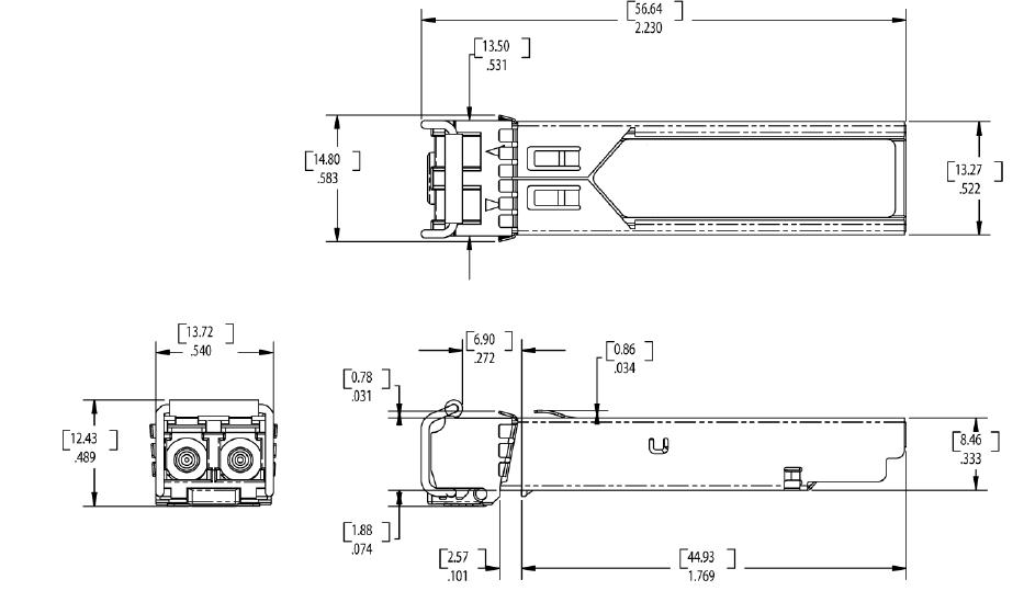
Ⅶ. Mechanical Specifications
PH-S3112-20LCD Small Form Factor Pluggable (SFP) transceivers are compatible with the dimensions defined by the SFP Multi-Sourcing Agreement (MSA).
Ⅷ.PCB Layout and Bezel Recommendations
Ⅸ. References
1. IEEE Std 802.3, 2002 Edition, Clause 38, PMD Type 1000BASE-LX. IEEE Standards Department, 2002.
2. “Fibre Channel Physical and Signaling Interface (FC-PH, FC-PH2, FC-PH3)”. American National Standard for Information Systems.
3. “Fibre Channel Physical Interface Specification (FC-PI-2 Rev. 10.0)”. American National Standard for Information Systems.
4. Small Form-factor Pluggable (SFP) Transceiver Multi-source Agreement (MSA), September 14, 2000.
5. Directive 2002/95/EC of the European Council Parliament and of the Council, “on the restriction of the use of certain hazardous substances in electrical and electronic equipment.” January 27, 2003.
